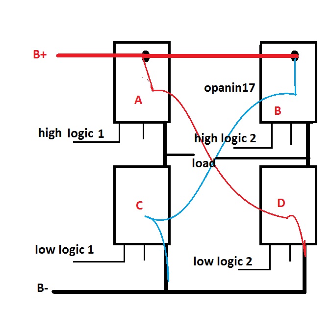
Bridge current diagram theory flow switches directions turned depending different were which off High voltage h-bridge What is an h-bridge?
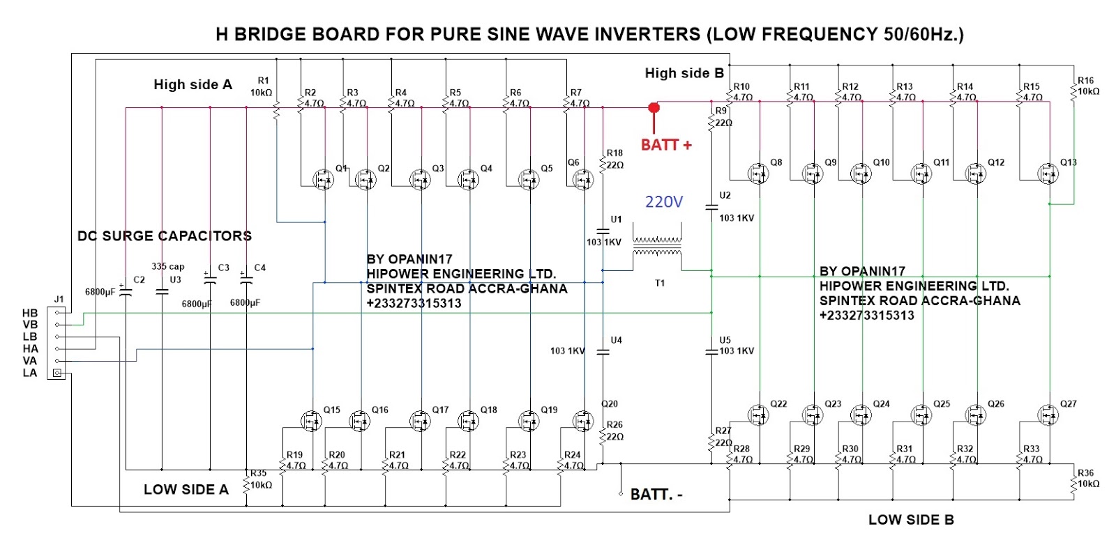
How to Design a H-Bridge Circuit for Modified Sine Wave Inverters
Electronic – motors and h-bridge – high current on pcb – valuable tech H bridge circuit diagram mosfet Bridge bjt npn motor dc transistors pnp circuit electronic transistor circuits collector 12v build switch driver nmos simple four make
Many circuits: h bridge
Bridge motor circuit transistor dc bipolar driver control hbridge transistors using peltier bjt schematic arduino pwm current npn mosfet schematicsElectronic circuit: h-bridge motor driver using bipolar transistors 2n2907a Bridge bjt circuit motor driver schematic full opto transistors pwm mosfets details arduino transistor hbridge dc ground duty voltage npnPonte circuito schematics electricalelibrary esquemático protoboard.
Mosfet outputs ele3 bristolwatchH-bridge: working, circuits and applications Bridge circuit mosfets using discrete basic layout figureDiscrete h-bridge circuit for enhanced vibration motor control.
Properly regards
H-bridge schematic with mosfet outputsCustom h-bridge circuit not working when adding motor Bridge voltage high isolated circuit electrical ask stackH-bridge (theory).
Pwm h bridge circuit diagramSchematic diagram of h-bridge H-bridge circuit designH bridge.

Driving a high current dc motor using an h-bridge
H bridge schematic diagramSchematic amplifier 2206 xr frequency ultrasonic varying A typical h-bridge circuitBridge mosfet circuit driver ci mos principle operation explain current expert answer voltage chip flow high.
H-bridge circuit? — parallax forumsSchematic diagram of h-bridge How to design a h-bridge circuit for modified sine wave invertersExplain the principle operation of the h bridge.
2: h-bridge circuit schematic.
What is an h-bridge?Circuit bridge wave sine full circuits modified diagram inverters transformer pwm output waveform Dc motor driver circuit using h-bridgeH-bridge circuit diagram..
Circuit schematic of h-bridge.Bridge circuit driver click inverters Bridge circuit work does schematic d882 pcb reverse engineered motor here stackIs this h bridge going to work properly?.

Bridge circuit time dead many circuits side switches never should two
Bridge circuit schematic electronic circuits beginnersMany circuits: heating solution for h bridge transistor circuits Electronic circuits for beginners: h bridge circuitCan you do an h-bridge w/ transistors?.
Solved the diagram below shows a typical h-bridgeH-bridge shoot through at high voltage problem Bridge motor dc switches circuits electronic build connect either backward spins depending forward conceptBridge circuit transistors motor using diodes connecting not relay high working when work mosfet transistor pnp circuits topic devices arduino.


H-Bridge (Theory)

How to Design a H-Bridge Circuit for Modified Sine Wave Inverters

H-Bridge shoot through at high voltage problem - Don't know the cause

H Bridge Circuit Diagram Mosfet

Explain the principle operation of the H bridge | Chegg.com

Is this H bridge going to work properly? | Forum for Electronics

H-bridge circuit diagram. | Download Scientific Diagram
